


19 "Rack Box-SUBRACK
Rear horizontal guide rail with insulating strip for backplane mounting
Shielding is usually 40 decibels at 1 GHz and 30 decibels at 2 GHz
Mounting load up to 11kg
▍subframe
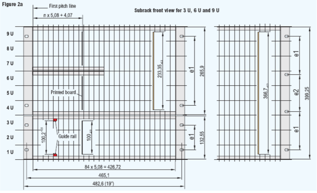
19 inch system dimensions and definitions:
The external dimension of the left and right flange of the sub-frame is 482.6mm(19 inches = 19*25.4=482.6), so it is called a 19-inch system.
width:
The maximum dimension in the width direction of the subrack (except for flanges) shall not be greater than 449mm, and the effective space stuck on the width of the subrack is in HP (or TE).
1HP (or TE)= 5.08mm (2/10 inch)
height:
The height dimension of the subrack is in U (or HE)
1U(HE)= 44.45mm (1-3/4 inch)
depth:
The depth of the subrack depends on the depth of the internal inserts, sockets and th90007
e Post-plug type not specified in the specification. The space allocated for each plug-in should be an integer multiple of HP.
Parts inserted into the subrack:
PCB-type plug-in unit consisting of a single PCB, front panel and connector.
Box-type plug-in unit, equipped with larger components, or can be installed multiple PCBs, can provide EMC functions.
▍sub-rack product ordering instructions
sub-frame is usually made of various aluminum alloy profiles and aluminum alloy plates. The surface treatment of aluminum alloy material is anodic oxidation.
The sub-rack is a customized product. Due to the PCB type and cassette type of the subrack, their size varies from user to user.
The width and height dimensions of the subrack are those specified according to IEC and IEEE standards. The depth dimension of the sub-frame can be customized according to customer requirements.
When customizing the subrack, the user must provide the panel structure size, the number of slot rails, and the required depth dimension.
subframe
▍The following are the data parameters of the cross-flow heat exchange core with an air volume of 1000~5000 m3/h
| Specification A* B *C/D |
heat exchange area (㎡) | efficiency (air volume m & sup3;/h)/(wind resistance Pa) | Dimensions (mm) | ||||||
| 40% | 45% | 50% | 55% | A | B | C | D | ||
| 350*350*350/3.5 |
12.25 |
1340/217.08 | 1020/126.8 | 765/71.9 | 555/38.2 | 300 | 300 | 300 | 3.5 |
| 400*400*400/3.8 | 16.84 | 1840/223.7 | 1400/130.1 | 1050/73.6 | 765/39.4 | 400 | 400 | 400 | 3.8 |
| 500*500*500/4.3 | 29.07 | 3180/254.2 | 2420/147.7 | 1820/83.9 | 1320/44.4 | 500 | 500 | 500 | 4.3 |
| 600*600*600/4.8 | 45.00 | 4920/273.6 | 3750/159.4 | 2820/90.4 | 2050/48.0 | 600 | 600 | 600 | 4.8 |
| 700*700*700/5.2 | 65.96 | 7200/309.1 | 5500/180.7 | 4130/102.1 | 3000/54.1 | 700 | 700 | 700 | 5.2 |